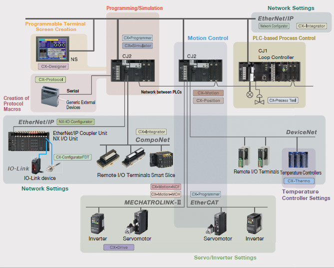

* Supported the V430-F series Auto Focus Multi Code Reader. * Supported the FHV7 series Smart Camera. * Supported the K6PM series Control Panel Monitoring Device. * Solved the problem that memory leak might occur when the project file could not be loaded. * Supported the new inverter 3G3RX2-series * Solved the problem that CX-Integrator might terminate abnormally when device parameters of the EJ1N-HFUB-DRT are copied. * Solved the problem that data could not be transferred to the comment memory immediately after clearing all memory. * Solved the problem in Ver.9.72 that arithmetic expressions cannot be used as the index of array variables in the ST program. * Solved the problem that no error is detected in program check even when an array variable without address assignment is used in a ST program/ST action/ST transition. * Solved the problem that transferring CP1E programs to CX-Simulator might fail when the programs include interruption tasks. * Solved the problem that a fatal error might occur in the PLC if a structure BOOL type member is used for the IF statement condition for the FBST program in CJ2H/CJ2M. * Solved the problem that program errors cannot be detected if an array of variable type index is specified in the DIFU/DIFD instruction operands in the FB ladder. * Solved the problem that an error occurs in the program check for a program with the maximum display capacity in the Memory view, when interrupt tasks and FB definitions are used simultaneously in a PLC with an area for FB only. * Solved the problem that the UM size displayed in the FB Memory view of CP1 might be incorrect when there is an FB definition and no FB instance. * Solved the problem that CX-Programmer might terminate abnormally, when a program that included FB instance was uploaded from the PLC. * Solved the problem that an error might not be detected in program check even though input condition of the FB instance was not correct.

* Solved the problem that timer/counter numbers were determined incorrectly as duplicated with CIO address when the CIO address was specified as automatic allocation area. * Solved the problem that a fatal error occurred on the PLC after the project was downloaded, becauseDR0+,IR00 that was specified for instruction's parameter was not detected in error check. * Solved the problem that CX-Programmer terminated abnormally or became inoperable when a project with a long project name or a long PLC name was loaded. When CX-One Lite is installed: CP1L-M => CP2E-S When CX-One is installed: CJ1M-CPU11 => CJ2M-CPU11 Each operation can use them in different ways.CP2E-EDR-A, CP2E-SD-, CP2E-ND. Flags work in different ways for different things, however. Then work bit W15.00 would be turned on when the timer elapsed and would remain on so long as the timer's input condition remained satisfied (ie: so long as 10.00 remains ON). If I had another rung where | T100 W15.00 Now, once 10.00 has been ON for two seconds, the timer will elapse and the flag for timer 100, T100, will turn ON. Say I have a 100ms timer, T100, which turns on when contact 10.00 is on: 10.00 _ You can use them as general booleans in your own programs, they can be parts of certain operations (ie: the CY (carry) flag is used on arithmetic operations which result in a carry - other flags are used to indicate overflows or div/0 errors, etc).Įdit again : (to answer extended question).Ī basic timer's completion flag is a contact with its number. You would use differentials in cases where you wanted to perform an action the moment a given condition changes.įlags can be used for almost anything. If the timer's number is, say T100 then you can use T100 as a contact in another rung of logic - it will be true when the timer's execution conditions are TRUE and the timer has expired.ĭifferentials (UP/DOWN) are special flags which are true for only one PLC scan (ie: they are true for one execution cycle only) when their input conditions change from FALSE to TRUE (ie:OFF to ON) for UP differentials, and TRUE to FALSE (ie:ON to OFF) for DOWN differentials. When the value reaches zero the timer's flag turns ON to indicate that it has expired. When the timer turns on it will begin counting and the PV (process value) will start from 300 and count down. If you use a BCD type 100ms timer and assign its SV (setpoint value) a BCD value of 300 then you have created a timer with a 30 second limit (300 x 100ms). These show time diagrams of most of the instructions and how each of the parameters and flags operate.įor example, a basic timer (TIM) works by assigning it a value. If you have CX-Programmer, a much better place to get information is the Instruction Reference (Help -> Instruction Reference -> yourPLC). Think of flags as interchangeable with the term "bit", "boolean", etc. PLCs are like any program - data is stored as different types.


 0 kommentar(er)
